You are in: Braided shunts
| Cross-section mm² |
A mm. |
B mm. |
S mm. |
Maximum current flow in Amps. | |||
| 50 Hz | 200 Hz | 1000 Hz | DC | ||||
| 25 | 20 | 20 | 3,7 | 150 | 140 | 130 | 150 |
| 50 | 20 | 20 | 5 | 250 | 230 | 200 | 250 |
| 75 | 20 | 20 | 7 | 340 | 310 | 270 | 350 |
| 100 | 20 | 20 | 9 | 370 | 340 | 300 | 380 |
| 75 | 30 | 30 | 5,2 | 390 | 360 | 340 | 400 |
| 100 | 30 | 30 | 6 | 440 | 420 | 380 | 450 |
| 150 | 30 | 30 | 8 | 540 | 510 | 420 | 550 |
| 100 | 40 | 40 | 5,2 | 480 | 440 | 400 | 500 |
| 150 | 40 | 40 | 6,8 | 590 | 540 | 480 | 600 |
| 200 | 40 | 40 | 8 | 680 | 630 | 500 | 700 |
| 250 | 40 | 40 | 10 | 780 | 690 | 550 | 800 |
| 150 | 50 | 50 | 6 | 640 | 590 | 540 | 660 |
| 200 | 50 | 50 | 7 | 760 | 700 | 610 | 780 |
| 250 | 50 | 50 | 8,3 | 870 | 800 | 630 | 920 |
| 300 | 50 | 50 | 10,6 | 920 | 830 | 750 | 950 |
| 200 | 60 | 60 | 6 | 830 | 760 | 680 | 880 |
| 250 | 60 | 60 | 7 | 900 | 830 | 650 | 950 |
| 300 | 60 | 60 | 8,5 | 970 | 870 | 620 | 1020 |
| 400 | 60 | 60 | 11,5 | 1100 | 980 | 780 | 1150 |
| 400 | 80 | 80 | 9,5 | 1200 | 910 | 670 | 1350 |
| 500 | 80 | 80 | 11 | 1400 | 1250 | 950 | 1500 |
| 600 | 80 | 80 | 12,5 | 1550 | 1350 | 980 | 1650 |
| 800 | 80 | 80 | 15,5 | 1800 | 1500 | 1100 | 1900 |
| 600 | 100 | 100 | 11,5 | 1700 | 1550 | 1150 | 1800 |
| 800 | 100 | 100 | 14 | 1900 | 1680 | 1200 | 1950 |
| 1000 | 100 | 100 | 16,5 | 2150 | 1850 | 1300 | 2300 |
| 1000 | 120 | 120 | 14,4 | 2300 | 2000 | 1400 | 2400 |
| 1200 | 120 | 120 | 16,5 | 2400 | 2150 | 1300 | 2500 |
| 1500 | 120 | 120 | 20 | 2500 | 2200 | 1400 | 2600 |
| 1800 | 120 | 150 | 20 | 2850 | 2450 | 1500 | 2950 |
| 2000 | 120 | 160 | 21 | 3200 | 2700 | 1600 | 3300 |
| 2500 | 120 | 180 | 23,5 | 3600 | 2900 | 1750 | 3700 |
| 3000 | 140 | 200 | 27 | 4000 | 3100 | 1900 | 4200 |
| 4000 | 140 | 220 | 34 | 5000 | 3300 | 2100 | 5300 |
The table above is indicative, the dimensions which are referenced are to be
considered as maximum dimensions and do not require difficult constructive
methods. The values of current flow shown above have been approximated.
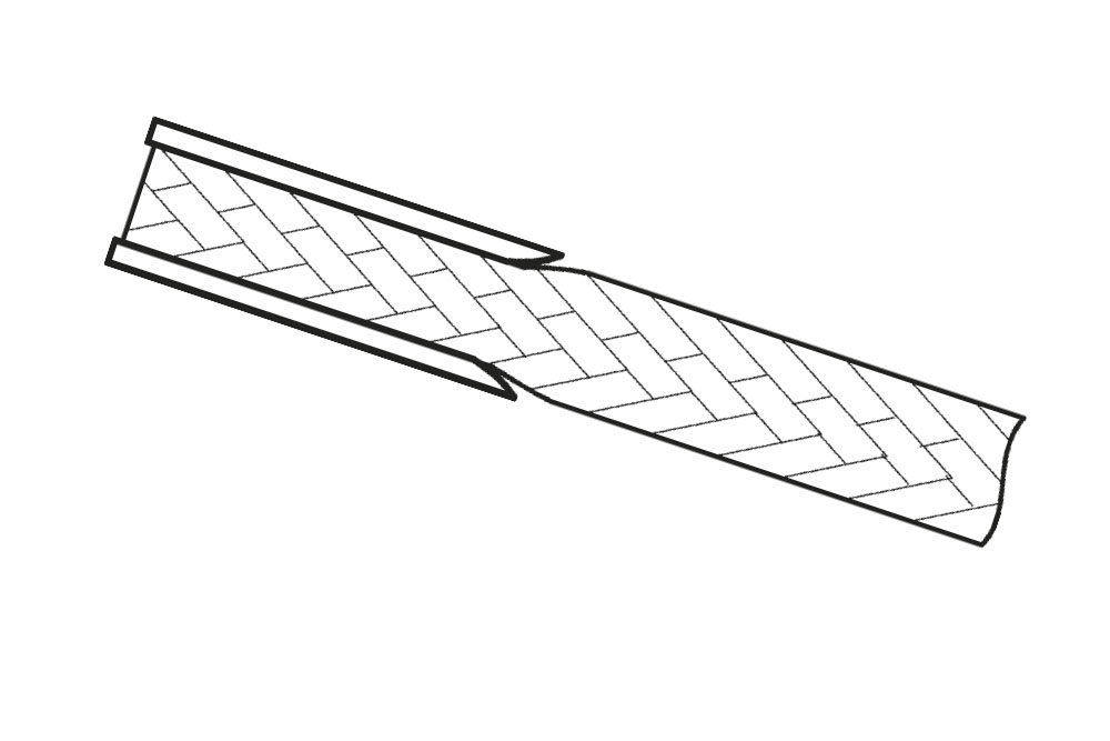
PRESSED TERMINALS
The braided ends are inserted into a tinned copper tube and
then pressed at high pressure, by a die, in order to obtain the
correct size. It is compacted to 80% therefore it is not necessary
to tin the internal part of the contact at a hot temperature; this
operation is performed only for special applications, and at
request.
Minimum cross-section: it is suggested to use a minimum
cross-section which is not less than 80% of the actual solid
bar’s cross-section (DIN 46276 specifications).